Smps Battery Charger Circuit Diagram

12v 5 Amp Transformerless Battery Charger Circuit Smps Based Battery Charger Circuit Power Supply Circuit Circuit Diagram

Homemade Circuit Projects 12v 5 Amp Transformerless Battery Charger Circuit Smps Based Battery Charger Circuit Power Supply Circuit Circuit Diagram

12v 5 Amp Transformerless Battery Charger Circuit Smps Based Battery Charger Circuit Power Supply Circuit Circuit Diagram

12v 5 Amp Smps Battery Charger Circuit Battery Charger Circuit Power Supply Circuit Circuit Projects

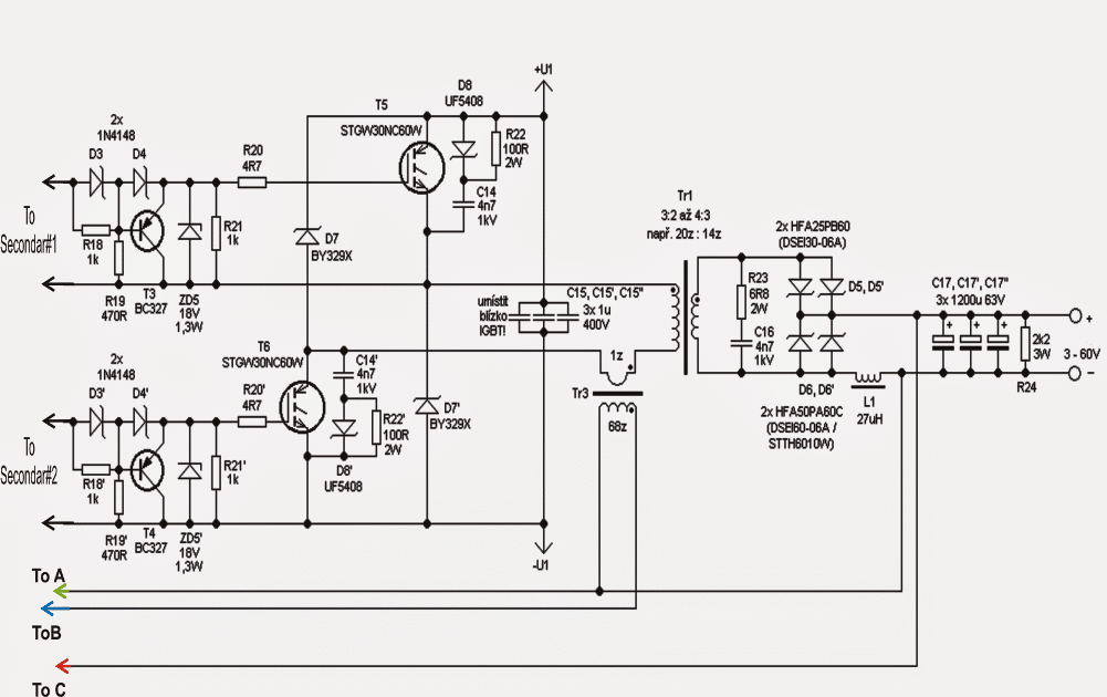
350w Smps Power Supply Circuit Power Supply Circuit Circuit Diagram Switched Mode Power Supply

This Is The Circuit Diagram Of 12v 10a Switching Power Supply The Circuit Shown In The Sche Power Supply Circuit Circuit Diagram Switched Mode Power Supply

A 12v battery is normally recharged at 14 2 v or 2 40v per cell.
Smps battery charger circuit diagram. This page contains a simple smps circuit which is capable of producing 12 volt dc with 1 amps current rating and this circuit contains few easily available components it may help you to design your own smps for your electronics projects. Usb cell phone charger circuit schematic most of the mobile phone battery is rated 3 6 volts at 1000 to 1300 mah. Battery charger battery circuit diagrams power supplies no comments 3 5 å for battery charging 14v smps modifiyesi get right bulent nur one of the projects with my teacher. Here the a high power mosfet becomes the main switching component and is used for triggering the ferrite primary winding with the set high frequency mains.
The proposed 12v 5 amp smps battery charger circuit employs a flyback converter topology which results in the required smps based high current compact mains isolated converter design. Battery charger flyback smps modifiyesi schematic circuit diagram on. Using a 3 pole switch you can choose the size of the voltage regulation. Electronics projects battery charger with flyback smps mod.
Before going to circuit diagram it is necessary to understand the operation of smps. Battery charger circuit power electronic projects smps circuits date 2019 03 20 14v 3 5 a smps modification for battery charging bülent nur is one of the projects that my husband announced. Hi swagatam ami battery byke charger toiri korchi 12volt 20amp battery ache 4te. The proposed 12v 5 amp smps battery charger circuit employs a flyback converter topology which results in the required smps based high current compact mains isolated converter design.
Switchmode charger smps schematic. Whereupon the position of the the left corresponds to the value of 7 2 v for battery motorcycle batteries with nominal voltage of 6v and position to the right corresponds to the value of 14 4 v for battery cars by nominal the value of 12v. These battery packs have 3 nimh or lithium cells having 1 2 volt rating. As the battery gets charged the terminal voltage begins increasing gradually until it reaches the set 14 2 v.
Ami ei page er 1st diagram ta toiri korbo thik korechi etay to hi voltage cut off ache kintu 12 volt er battery te full charge hole 14 2 volt hoy se karon e mot voltage hobe 56 8 volt ba pray 57 volt ei circuit daigram e sei voltage e cut. Here the a high power mosfet becomes the main switching component and is used for triggering the ferrite primary winding with the set high frequency mains rectified dc. Once we attach the charger with the battery voltage drops from the actual supply 14 2 v level to the discharged level of the battery.

12v 5 Amp Transformerless Battery Charger Circuit Smps Based Battery Charger Circuit Battery Charger Circuit

Simple Switching Power Supply 15 Watt Power Supply Circuits Power Supply Circuit Power Supply Design Power Supply

12v 5 Amp Transformerless Battery Charger Circuit Smps Based Battery Charger Circuit Power Supply Circuit Circuit Diagram

12v 5 Amp Transformerless Battery Charger Circuit Smps Based Battery Charger Circuit Power Supply Circuit Circuit Diagram

Simple Smps Circuit Circuit Diagram Circuit Design Circuit

60 Volt Switching Power Supply For Pa Power Supply Circuits Switched Mode Power Supply Power Supply Circuit Power Supply

12v 5 Amp Transformerless Battery Charger Circuit Smps Based Battery Charger Circuit Power Supply Circuit Circuit Diagram

220v Smps Cell Phone Charger Circuit Homemade Circuit Projects Cell Phone Charger Circuit Diagram Circuit Projects

The Post Details A Simple 12v 2 Amp Smps Circuit Which Can Be Used For All Offline Flyback Converter Appli Circuit Projects Electronic Circuit Projects Circuit

Adjustable Smps Laboratory Power Supply Ucc28600 0 30v 5a Ucc28600 Adjustable Smps Circuit Schematic Power Supply Circuit Power Supply Electronic Schematics

Simple 1a 12v Smps Full Circuit Diagram With Explanation Electronics Circuit Power Supply Circuit Circuit

Adjustable 0 100v 50 Amp Smps Circuit Circuit Projects Electronic Circuit Projects Circuit
12v 5a De Alimentare Cu Comutare Switched Mode Power Supply Power Supply Power Supply Circuit

Adjustable Smps Laboratory Power Supply Ucc28600 0 30v 5a Ucc28600 Adjustable Smps Circuit Schematic Power Supply Circuit Power Supply Electronic Schematics

Simple 12v 1 Amp Smps With Pcb And Transformer Winding Details Electronic Circuit Projects Electronic Schematics Power Supply Circuit

Image Result For 15v 1a Smps Circuit Diagram Circuit Diagram Circuit Power Supply Circuit

12v 5a Switched Power Supply Switched Mode Power Supply Power Supply Power Supply Circuit

12v Battery Charger Detailed Project With Circuit Available In 2020 Battery Charger Circuit Battery Charger Charger
1

5v 10a 50w Offline Switching Power Supply Power Supply Circuit Power Supply Circuit Diagram

Simple 3 3v 5v 9v Smps Circuit In 2020 Power Supply Circuit Circuit Projects Power Supply
8z3phly1wghtdm

12 Volt 2 A Switching Power Supply Power Supply Power Supply Circuit Circuit Diagram

2x100v 500w Audio Amplifier Smps Power Supply Switchmode Uc3844 2x100v Smps Circuit Schematic 120x120 Circuit Diagram Audio Amplifier Power Supply Circuit

Pin On Battery Charger Circuit

Looking For A Cool And Simple To Build 12v 2 Amp Smps Circuit Please Go Through The Details Under This Ar Circuit Projects Electronic Circuit Projects Circuit

Switching Mode Power Supply 10a 20 50v Dc Ct Electronic Circuit Power Supply Circuit Switched Mode Power Supply Circuit Diagram

12 Volt 2 A Switching Power Supply Power Supply Power Supply Circuit Circuit Diagram

350 Watt Smps Circuit For Audio Amplifiers Circuit Projects Electronics Circuit Circuit

6v And 12v Car Battery Charger Circuit Design Battery Charger Circuit Car Battery Charger Circuit Design

Switching Power Suplly For Color Television Circuit Electronic Circuit Color Television Power Diagram Design

12v 7ah Smart Battery Charger Battery Charger 12v Battery Charger Circuit Battery Charger

Make Cheap 6v Battery Charger Circuit From Mobile Charger Eleccircuit Com Battery Charger Circuit Mobile Charger Battery Charger

10a 70v Smps For Power Amplifier Power Supply Circuit Switched Mode Power Supply Electronics Circuit

Battery Charger Circuit With 4 Led Indicator Battery Charger Circuit Solar Battery Charger Automatic Battery Charger

Battery Charger Overcharge Protection Battery Charger Circuit Battery Charger Charger

This Article Will Illustrate A Simple Procedure To Devise An Unregulated 50v Switching Smps Symmetric Pow Power Supply Circuit Audio Amplifier Circuit Projects

Pwm Solar Battery Charger Circuit Homemade Circuit Projects Solar Battery Charger Battery Charger Circuit Solar Battery

Self Oscillating Smps Circuit Flyback 600w 60v 120khz 600w Smps Circuit Schematic Self Osc Electronics Circuit Power Supply Circuit Electronic Circuit Projects

Smps 2 X 50v 350w Circuit For Audio Power Amplifiers Homemade Circuit Projects Power Supply Circuit Audio Amplifier Circuit Projects

12v 5 Amp Smps Battery Charger Circuit Battery Charger Circuit

In This Particular Posting We Find Tips To Build Up A Simple 6v 12v 24v Battery C Battery Charger Circuit Automatic Battery Charger Universal Battery Charger

